Installing Rock Sliders on the L663 Defender: Structural Mounting and Corrosion Mitigation
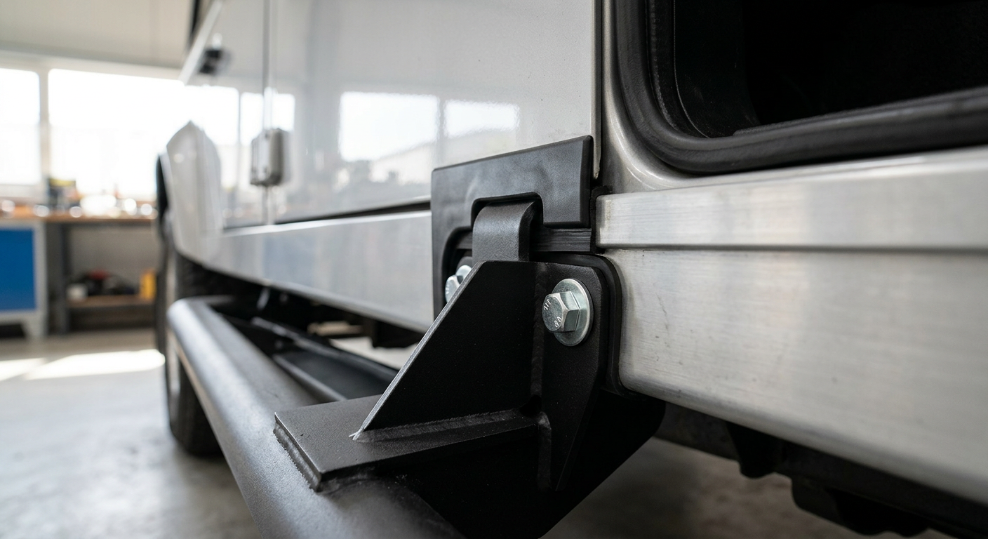
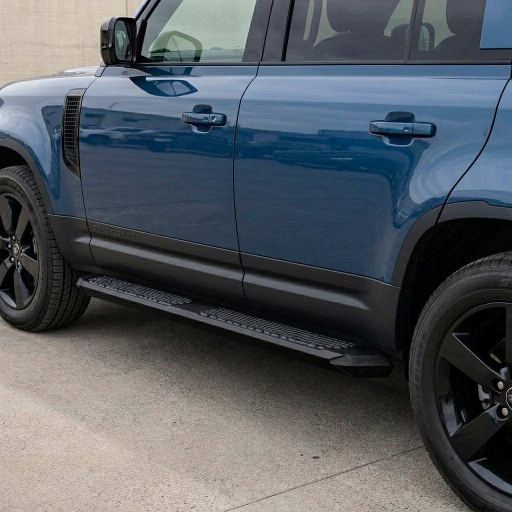
Fitting heavy-duty rock sliders to the L663 Land Rover Defender requires a completely different approach than traditional body-on-frame 4x4s. Because the modern Defender uses an aluminium monocoque (D7x architecture), securing side protection means interfacing steel brackets directly with aluminium structures. This technical guide explains how to safely mount rock sliders, navigate hidden wiring harnesses and air lines, prevent destructive galvanic corrosion, and preserve critical vehicle jacking points.
The L663 Unibody Challenge: Why Sliders Aren't Just Bolted On
Traditional body-on-frame four-wheel drives allow rock sliders to be clamped or welded directly to heavy-gauge steel frame rails. The L663 Defender, built on Land Rover’s D7x aluminium monocoque architecture, has no such frame. Instead, it relies on an ultra-stiff, lightweight aluminium unibody structure. Because of this design, aftermarket rock sliders cannot simply be bolted to a chassis rail; they must interface directly with the vertical sill structures, inner floor pan reinforcements, and factory subframe mounting points. Understanding this structural difference is critical before starting any physical installation.
When an L663 strikes an obstacle on the trail, the rock slider must transfer the impact energy across a wide surface area of the monocoque to prevent local deformation of the aluminium panels. High-quality sliders achieve this by utilizing complex, multi-point mounting brackets that wrap around the vehicle's structural rocker channels. These brackets anchor into existing threaded holes within the inner steel-reinforced box sections. Relying on single-point attachments or failing to distribute loads vertically and horizontally along the sill can lead to structural tearing of the aluminium floor pan during heavy lateral or vertical impacts.
Addressing Galvanic Corrosion: Dissimilar Metals in the L663 Sill
One of the most critical aspects of installing aftermarket parts on the L663 Defender is managing the contact between dissimilar metals. Most heavy-duty rock sliders are fabricated from structural carbon steel for maximum impact resistance. However, when steel is placed in direct contact with the Defender’s aluminium body panels in the presence of moisture and road salt, a galvanic cell is created. The aluminium acts as an anode and the steel acts as a cathode, resulting in rapid, destructive corrosion of the vehicle's structural aluminium sills.
To mitigate this risk, DIY installers must ensure complete electrical isolation between the steel mounting brackets and the aluminium body. This is achieved by installing non-conductive barriers, such as heavy-duty EPDM rubber gaskets, structural polyurethane isolation tape, or specialized high-density polyethylene (HDPE) spacers between all mating surfaces. Furthermore, any fasteners used must be coated with a sacrificial zinc-nickel or Dacromet finish, rather than raw steel or standard zinc plating. Applying a liberal layer of non-conductive, anti-corrosion paste (such as Tef-Gel or a high-quality zinc-rich primer) inside the mounting holes and on the threads of the bolts provides an extra layer of defense against moisture intrusion.
Navigating the Sill Channels: Wiring, Air Lines, and ECU Clearance
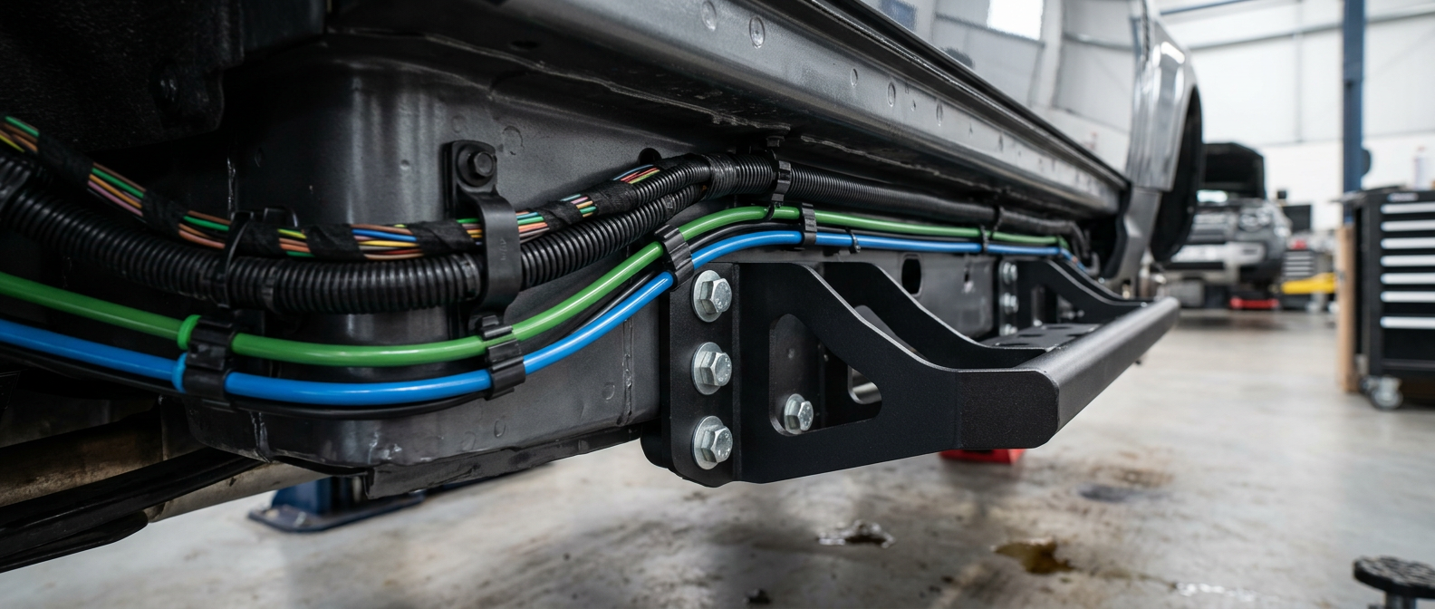
Before drilling any holes or mounting brackets, you must understand what lies behind the factory plastic sill covers. The rocker channels of the L663 are packed with critical vehicle infrastructure. On the left and right sides of the vehicle, main wiring looms run through protective plastic trays parallel to the sills. Additionally, on models equipped with electronic air suspension, the high-pressure plastic air lines and their routing clips run directly along the driver-side sill frame to feed the reservoir tank and the air springs.
During installation, aftermarket brackets must pass through or around these channels. If a bracket is clamped tightly against a wiring harness or an air line, vibrations during off-road driving will cause the steel edge to chafe through the insulation or plastic tubing. This can lead to instantaneous communication faults on the CAN-bus network, or a sudden loss of suspension pressure. Installers must carefully route all wiring harnesses and air lines away from the slider brackets, using heavy-duty cable ties and split-conduit wrap where necessary to ensure at least 10mm of clearance from any metal edges.
Preparing and Trimming the OEM Plastic Sill Covers
To install structural rock sliders, you must first remove the factory plastic rocker panels (sill covers). These panels are held in place by a series of plastic trim clips and screws located along the underside and inside the wheel arches. Removing them requires a steady hand to avoid snapping the fragile plastic mounting tabs on the body side. Once removed, you are faced with a choice: leave the plastic covers off entirely, or trim them to fit around the new slider brackets to maintain a factory-sealed appearance.
Trimming the plastic sill covers is highly recommended because it prevents mud, salt, and debris from accumulating in the exposed structural cavities of the monocoque. To do this accurately, hold the rock slider brackets up to the vehicle to mark the exact locations of the mounting arms. Using an oscillating multi-tool or a rotary tool with a plastic-cutting disc, carefully cut out slots in the plastic cover to allow the slider arms to pass through. Sand the cut edges smooth and reinstall the plastic covers using new OEM-spec trim clips to ensure a tight, rattle-free seal before final-bolting the sliders.
Bolting Up and Torque Sequences for Structural Integrity
The fastening phase of the installation requires strict adherence to torque specifications to prevent stripping the factory threaded inserts. The L663 uses a combination of pre-existing M8 and M10 threaded holes in the structural steel subframe mounts and inner sill sections. Because these threads are often exposed to road debris prior to installation, they must be thoroughly cleaned using a wire thread brush and compressed air. Running a thread chaser tap through the holes is highly recommended to clear out road grime and factory underbody wax.
When mounting the sliders, start by hand-threading all fasteners to ensure they are not cross-threaded into the chassis inserts. Once all bolts are loosely installed and the slider is aligned parallel to the bodywork, begin torqueing them in a staged sequence. Work from the center mounting brackets outward to the front and rear mounts to distribute the clamping force evenly. M8 fasteners should typically be torqued to 25 Nm (18 lb-ft), while M10 fasteners require 45 to 50 Nm (33 to 37 lb-ft), depending on the grade of the hardware. Always use a calibrated torque wrench; over-tightening can easily strip the internal threads out of the vehicle's structural mounting plates.
Preserving Jacking Points and Air Suspension Clearances
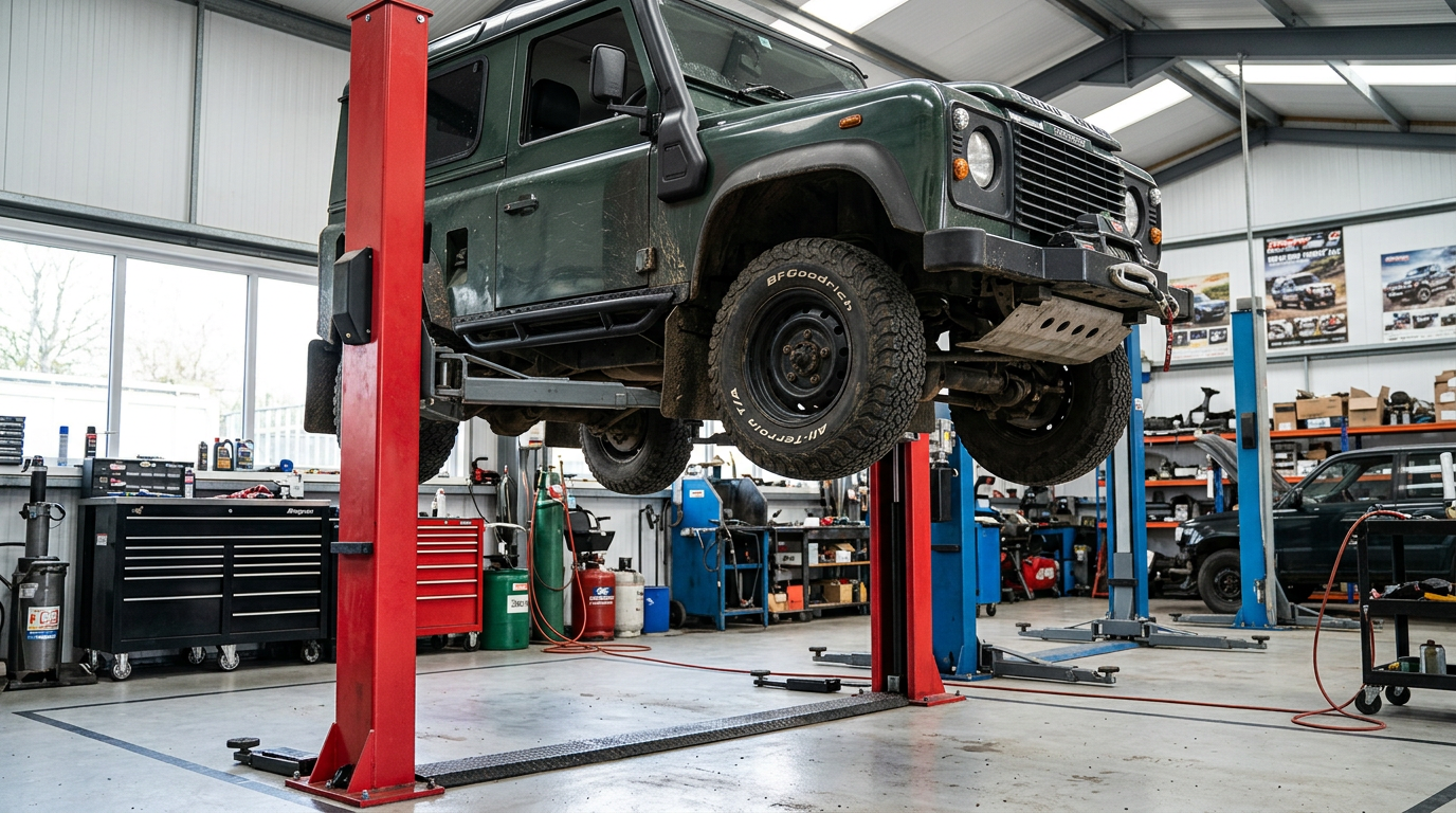
A major consideration when selecting and installing rock sliders is how they affect the vehicle's usability on and off the trail. The L663 has specific, reinforced jacking points located on the underside of the sills. Well-designed rock sliders will either preserve access to these factory jacking points or incorporate dedicated, reinforced lifting slots along their outer rails. These slots are designed to safely accept the tongue of a high-lift jack or the lifting pads of a standard workshop two-post hoist without slipping.
Additionally, you must verify that the installed sliders do not interfere with the natural articulation of the suspension. On air-sprung models, the suspension components move through a wide range of travel, and the air bags expand under load. Ensure there is a minimum of 20mm of clearance between the innermost points of the slider brackets and any moving suspension linkages or the flexible rubber boots of the air springs. After completing the installation, cycle the vehicle through its full height range—from Access Height to Off-Road 2—while visually inspecting the clearances from underneath to confirm that no contact occurs.