On-Board Air Compressor Integration for the L663 Land Rover Defender
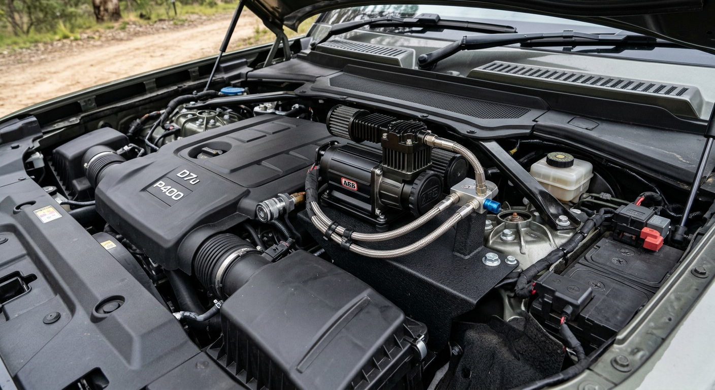
Integrating a high-output, on-board air compressor into the modern Land Rover Defender requires navigating tight engine bays, complex interior trim, and a highly sensitive electrical architecture. This technical guide covers physical mounting options, plumbing strategies, and how to safely wire high-draw compressors without disrupting the vehicle's Intelligent Battery Sensor (IBS) or triggering CAN bus faults.
The Packaging Dilemma: Selecting the Optimum Mount Location
Integrating an on-board air compressor into the L663 Defender (90, 110, or 130) presents immediate spatial challenges. Unlike traditional body-on-frame utility vehicles with cavernous engine bays and simple metal inner guards, the L663 features a highly packed engine compartment and a tightly tailored interior. For DIY installers, there are two primary zones for mounting a high-output compressor: the engine bay firewall area or the rear loadspace quarter-panels.
An engine bay installation is preferred by those who want to keep the interior free of noise and heat. Brackets designed for the L663 typically bolt to existing mounting points near the right-side or left-side strut towers, depending on engine configuration (D250/D300 diesel vs. P300/P400 petrol). However, the engine bay of a modern Defender experiences extreme thermal load, especially in turbocharged inline-six variants. If you mount a compressor here, it must be rated for high ambient operating temperatures, and the intake filters must be routed away from direct engine heat.
The alternative is utilizing the unused cavities behind the rear loadspace trim panels. In the Defender 110 and 130, the space behind the right-hand side trunk trim (often housing the factory jack or tool kit) can accommodate a compact twin-compressor unit. This keeps the unit shielded from road grime, water, and engine heat. The drawback is the loss of internal storage space, the necessity of cutting trim panels for access and ventilation, and the transmission of compressor vibration and noise directly into the passenger cabin.
Electrical Integration: Navigating the Intelligent Battery Sensor (IBS)
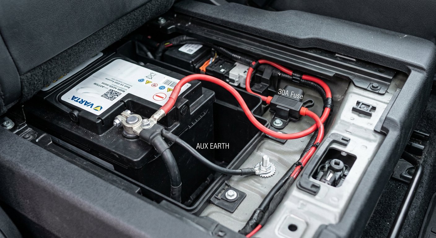
The L663 Defender utilizes an advanced electrical architecture managed by a Body Control Module (BCM) and an Intelligent Battery Sensor (IBS) located on the negative battery terminal. The battery itself is located under the front passenger seat (on Left-Hand Drive vehicles) or driver seat (on Right-Hand Drive vehicles). High-output twin compressors, such as the ARB Twin, can draw up to 56 Amps at maximum working pressure. Wiring this system incorrectly will trigger charging system faults, disable the auto start-stop system, and cause premature battery degradation.
When wiring the compressor, the positive lead must be connected directly to the positive battery terminal or the main unswitched busbar in the under-seat battery compartment, using an inline fuse rated for the compressor's maximum draw (typically 60A to 80A). Crucially, the negative ground cable must never be connected directly to the negative battery terminal post. If you bypass the IBS by connecting directly to the post, the BCM cannot measure the current drawn or returned to the battery during compressor operation, throwing off its State of Charge (SoC) calculations.
To avoid this, locate the factory chassis ground point outside the battery box (or the dedicated ground stud on the vehicle body near the battery compartment). Connecting the compressor's negative lead to this chassis ground ensures that all current flows through the IBS shunt resistor, allowing the vehicle's power management system to accurately monitor the load and adjust alternator output accordingly. Use minimum 8 AWG high-temperature cross-linked polyethylene (XLPE) insulated wire for the main power runs to minimize voltage drop.
Plumbing and Hose Routing: Heat Management and Air Flow
An air compressor compressing atmospheric air to 100+ PSI generates significant heat at the outlet port, often exceeding 140 degrees Celsius during sustained operation. Standard polyurethane or nylon air hoses connected directly to the compressor outlet will melt or burst under these conditions. The first 1 to 1.5 meters of plumbing from the compressor outlet must consist of high-temperature PTFE (Teflon) lined, stainless steel braided hose.
Once the air has traveled through this metallic run and cooled slightly, you can transition to heavy-duty DOT-approved nylon or polyurethane tubing. For a clean installation, route this tubing from the mounting location to external bulkhead quick-connect couplers. Popular mounting points for these couplers include the front grille mesh, the rear bumper skin (adjacent to the towing eye), or inside the exterior side gear boxes if fitted.
When routing lines beneath the vehicle chassis, stay clear of moving suspension components—especially the air lines and control arms of the air suspension system—and shield the tubing from exhaust heat sources. Use high-quality rubber-lined P-clamps to secure the lines to the subframe, ensuring there is sufficient slack to account for chassis flex and engine movement if routing from the engine bay.
Control Circuits: Safe Switching and Avoiding CAN Bus Faults
To operate the compressor, you need a control switch that triggers the compressor's internal relay. Do not attempt to tap into the L663's factory dashboard switches or splice directly into existing cabin wiring harnesses. The Defender's switches operate on low-voltage multiplexed LIN/CAN bus networks; tapping these lines will cause immediate communication faults and potential module damage.
Instead, use an isolated control circuit. Run a 12V ignition-switched source to trigger your compressor switch. A safe, clean source for this ignition-switched signal can be found at the rear accessory/cigar lighter socket fuse in the loadspace fuse box. Alternatively, you can use a solid-state power distribution module (such as a Garmin PowerSwitch or Auxbeam system) connected directly to the battery, which controls the compressor via a wireless Bluetooth connection or a single, isolated control wire run through the firewall grommet.
If you are mounting the control switch physically in the cabin, the rubber firewall grommet located behind the engine block (accessible from the passenger footwell) is the cleanest path to route the switch wires. Ensure you use a step-drill or sharp awl to pierce the outer membrane of the grommet, and seal the entry point with automotive-grade silicone sealant to maintain the vehicle's wading depth capability of 900mm.
Air Filtration and Moisture Mitigation in Confined Spaces
For an on-board compressor to survive off-road conditions, it must breathe clean, dry air. If you mount the compressor in the rear quarter-panel cavity, the air inside that panel can become hot and dusty, especially on corrugated gravel roads where dust ingress through body vents is common. If mounted in the engine bay, the intake is exposed to road spray, dust, and heat.
To mitigate this, utilize remote intake filter kits. These kits allow you to run flexible, small-diameter hoses from the compressor's intake ports to a cleaner, more protected area. For engine bay mounts, route the intake filters high up near the cowl panel or inside the airbox outer fender intake track. For rear interior mounts, route the intake lines to draw air from the climate-controlled main passenger cabin rather than the dusty, uninsulated panel cavities.
Additionally, compressing air concentrates atmospheric moisture. If you use air tools, lockouts, or frequently inflate large tyres (such as 33-inch or 35-inch terrain tyres), install an inline water separator/filter immediately after the high-temperature braided hose run. This prevents moisture from pooling inside the storage lines or being pumped directly into your tyres, which can corrode wheels and damage tyre pressure monitoring sensors (TPMS).