Fitting a Discrete Winch to the L663 Defender: Structural and Electrical Integration
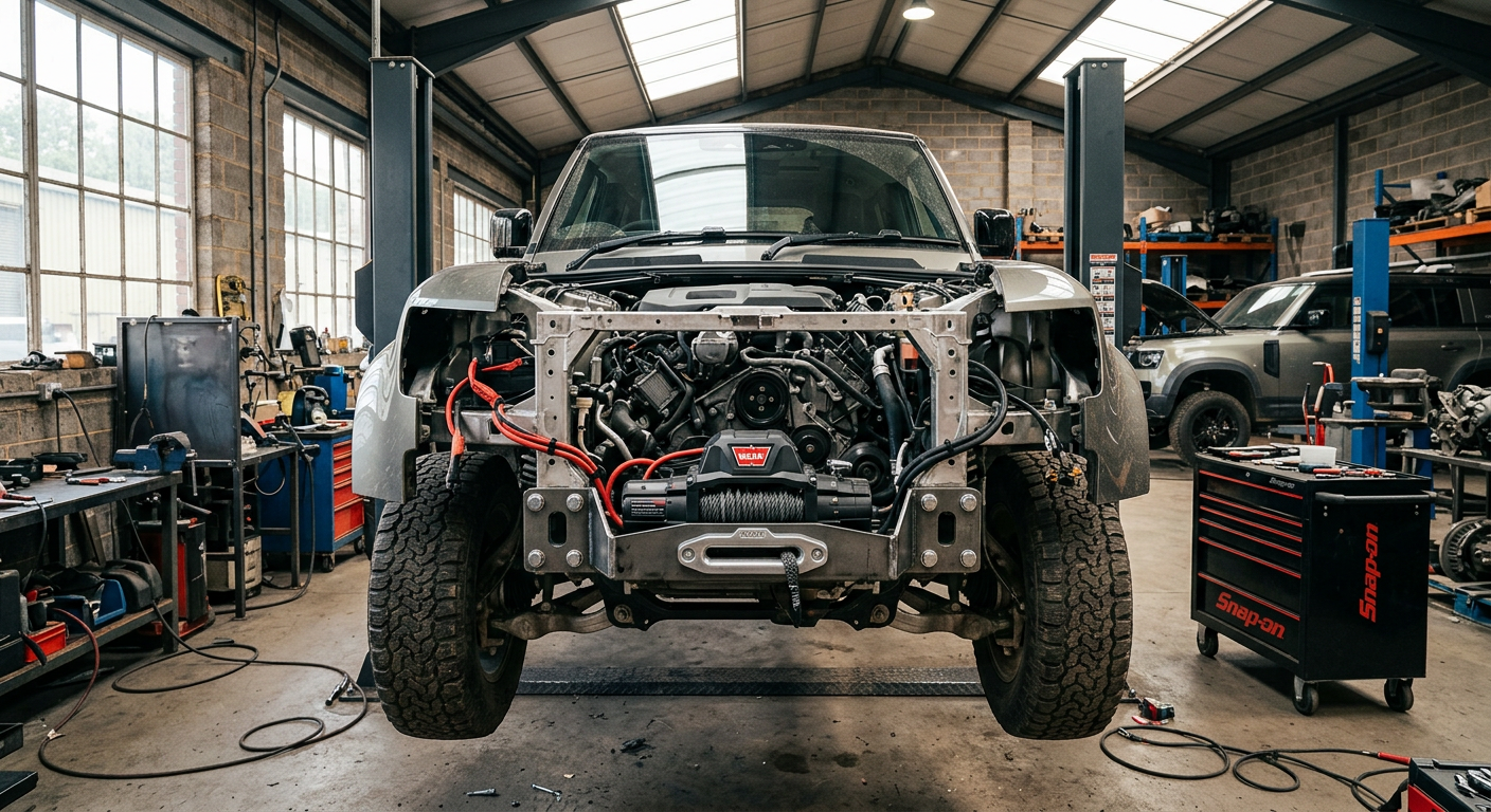
Installing a recovery winch on the modern unibody Land Rover Defender requires precise structural integration, heavy-gauge electrical routing, and careful recalibration of driver-assistance sensors. This technical guide explains how to fit a discrete winch cradle to your L663 without compromising cooling efficiency or ADAS safety systems.
Structural Integration and Unibody Subframe Mounting
Unlike its predecessor, the L663 Land Rover Defender does not feature a traditional steel ladder frame. Instead, it utilizes an aluminum-intensive D7x monocoque architecture with bolt-on front and rear steel subframes. Because there are no chassis rails to bolt a traditional winch bumper to, a discrete winch setup requires an engineered steel cradle that bolts directly to the vehicle's structural subframe mounting nodes. This cradle replaces the factory aluminum crash beam behind the plastic bumper fascia, assuming its role as a structural crossmember while providing a secure mounting pocket for the winch.
When installing a discrete winch tray, you must utilize the factory bumper beam mounting points on the front of the frame horns. These mounts typically use heavy-duty M10 and M12 fasteners. It is critical to use Class 10.9 or 12.9 high-tensile hardware, torqued precisely to manufacturer specifications (typically 55 Nm for M10 and 95 Nm for M12, though you must reference your specific cradle manufacturer's documentation). Because the winch cradle ties the two frame horns together structurally, any misalignment during installation can introduce torsional stress to the front subframe, leading to tracking issues or premature wear on suspension components.
Furthermore, because the winch pulling forces are transferred directly to the monocoque platform, using a bridle or pulling at extreme angles requires extreme caution. The structural cradle must distribute loads evenly across both frame horns. Single-point off-angle pulls can concentrate forces on one side of the subframe, risking deformation of the aluminum mounting ears. DIY installers must ensure the cradle is perfectly squared to the vehicle center line before final torque is applied to the mounting bolts.
Managing Cooling Pack Clearances and Airflow Shrouding
Directly behind the L663's front bumper lies a densely packed cooling module. Depending on your engine variant—be it the P300 four-cylinder, P400 mild-hybrid inline-six, D300 diesel, or the supercharged V8—this assembly consists of the main engine radiator, the charge-air cooler (intercooler), the air conditioning condenser, and auxiliary low-temperature radiators situated in the lower corners. Fitting a winch into this tight space requires removing or heavily modifying the factory plastic air ducting and shrouds that channel airflow through these heat exchangers.
The primary challenge is ensuring the winch motor and drum assembly do not press against or rub the delicate aluminum fins of the air conditioning condenser or intercooler. Even minor vibrations during off-road driving can cause the winch housing to wear a hole through a cooling core. Installers must maintain a minimum clearance of 15mm between the winch assembly and the cooling pack. If necessary, defensive rubber bump-strips or spacer spacers should be integrated to prevent physical contact under chassis flex.
Modifying the plastic ducting also alters the aerodynamics of the cooling system. While it is tempting to discard the factory plastic shrouds entirely to make room for the winch, doing so allows air to bypass the radiators, reducing cooling efficiency under high loads or when towing. You must carefully trim the factory shrouds using a rotary tool, removing only the material strictly necessary to clear the winch body, and then seal the remaining duct edges with heavy-duty foam tape to preserve the negative pressure zone behind the grille.
High-Current Electrical Routing from the Engine Bay
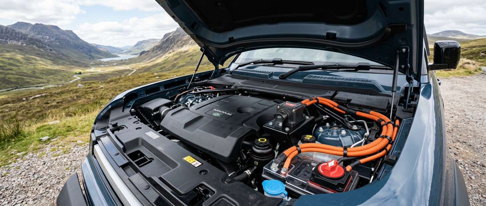
A recovery winch drawing up to 450 amps under full load requires a robust, low-resistance electrical path to prevent voltage drops and thermal runaway. In the L663 Defender, the main starter battery is located under the front passenger seat (or driver's seat in right-hand-drive markets). Running heavy-gauge cabling from the interior cabin to the front bumper is highly impractical and introduces significant risk of cable chaffing through the firewall. Instead, the winch must be wired directly to the high-current distribution terminals located under the hood in the engine bay.
The positive connection should be made at the dedicated jump-start terminal block on the firewall, using at least 2/0 AWG (67 mm²) multi-strand copper cable with tinned ends to resist corrosion. Never ground the winch to the aluminum body panels; aluminum is a poor conductor compared to copper and steel, and doing so will cause severe galvanic corrosion and electrical noise. The ground cable must run directly to the main steel chassis ground stud located on the frame horn near the engine mount.
Safety dictates the installation of a heavy-duty manual isolator switch or a high-current solid-state contactor in the positive line. This allows the winch electrical system to remain completely de-energized during daily road driving, preventing a catastrophic short circuit in the event of a front-end collision. Mount the isolator switch in an accessible location under the hood, near the fuse box, using a custom bracket that does not drill into any structural aluminum panels. All high-current cabling must be sleeved in flame-retardant split conduit and secured away from heat sources and moving suspension components.
Navigating ADAS, Radar, and Parking Sensor Obstructions
The front bumper of the modern Defender is a highly active technological zone. It houses six ultrasonic parking sensors, the forward-facing 3D surround camera, and, most critically, the mid-range radar sensor used for Adaptive Cruise Control (ACC) and Emergency Braking. When installing a discrete winch, the physical position of these sensors must not be altered, and their fields of view must remain entirely unobstructed by the hawse fairlead, winch hook, or recovery shackles.
The ACC radar module sits centrally in the lower bumper grille. Many aftermarket discrete winch cradles require relocating this radar module slightly upward or to the side. If the radar bracket is moved even a few millimeters, or if its vertical angle is altered by as little as one degree, the system will throw a calibration fault and disable cruise control and emergency braking. If relocation is required, ensure the new bracket is absolutely rigid; any vibration of the radar module while driving will cause sensor drift and system shutdown.
Similarly, the ultrasonic parking sensors are highly sensitive to nearby metallic objects. If the fairlead or winch hook protrudes too close to the inner-center sensors, they will falsely register an obstacle. DIYers must drill precise holes in the new plastic bumper trim inserts to house the factory sensor clips at their original angles. Once the installation is complete, the vehicle may require a dynamic radar calibration. This can sometimes be self-calibrated by driving on marked roads, but occasionally requires a diagnostic tool like TOPIx Cloud or Pathfinder to reset the yaw and pitch offset values.
Precision Bumper Cutting and Fascia Reconstruction
Integrating a discrete winch requires permanently modifying the factory plastic front bumper fascia to allow access to the synthetic line, hawse fairlead, and clutch lever. This step requires patience and precision to maintain the vehicle's clean aesthetic. Before making any cuts, apply high-quality masking tape over the entire work area to prevent the bumper plastic from scratching and to provide a clear surface for marking your cut lines.
Use the manufacturer-provided paper template as a starting guide, but always verify the measurements against the physical winch cradle mounted on the vehicle. Use a rotary tool with a plastic-cutting spiral bit or a fine-toothed jigsaw at medium speed to avoid melting the ABS plastic. Keep your cut approximately 2mm inside the final line, then use a hand file and a deburring tool to smooth the edges down to the final dimensions. This technique prevents the plastic from tearing and results in a factory-quality edge.
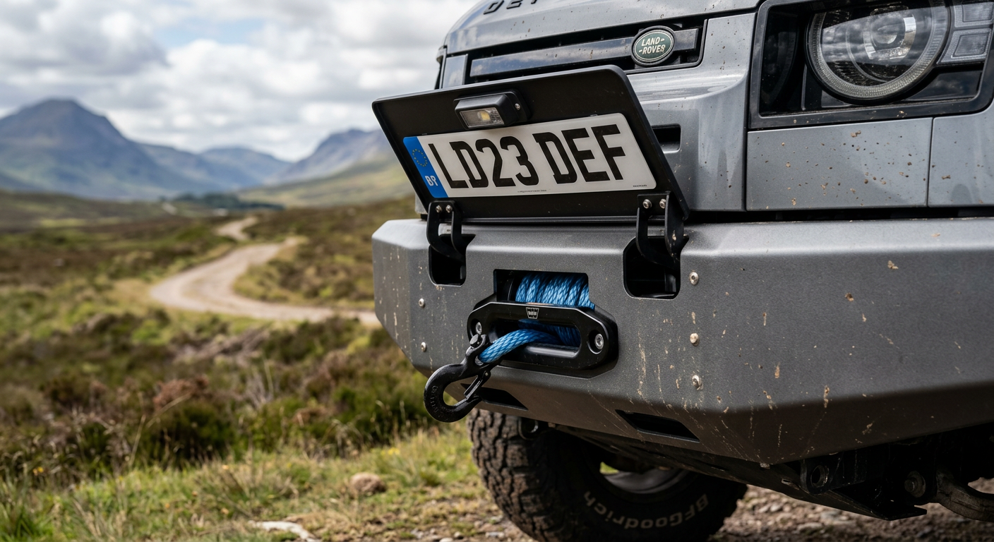
The license plate mounting position must also be addressed, as it normally sits directly over the area where the fairlead emerges. The standard solution is a flip-up license plate bracket that bolts to the top of the hawse fairlead. When the winch is not in use, the plate flips down to cover the fairlead and hook, keeping the vehicle road-legal and protecting the synthetic rope from UV degradation. Ensure the flip-up hinge is tensioned or secured with spring clips so it does not bounce or rattle at highway speeds.
Solenoid Relocation and Clutch Lever Accessibility
Because a discrete winch is tucked completely behind the bumper skin, accessing the manual free-spool clutch lever and the control box plug can be exceptionally difficult. Standard winches have the solenoid (contactor) box mounted directly over the drum, which is physically impossible in the tight confines of the L663 engine bay. The contactor box must be relocated.
The ideal relocation site is inside the engine bay, mounted to a fabricator bracket near the engine bay fuse box or behind the passenger-side headlight housing. This keeps the sensitive electrical relays dry, clean, and away from road grime and deep water crossings. To connect the winch controller, you can extend the remote socket wiring to a flush-mount marine-grade port installed on the plastic radiator cover panel under the hood, or opt for a wireless remote system.
Accessing the clutch lever to free-spool the synthetic line presents another packaging hurdle. Some installers cut a small hand-access port in the top plastic radiator shroud, allowing you to reach down to turn the lever. Alternatively, you can rotate the winch gearbox housing prior to installation so that the clutch lever points downward, allowing access from beneath the bumper, though this exposes your arm to ground debris when engaging the winch. A more advanced option is fitting a winch with an air-actuated clutch system, which uses a small 12V air solenoid to engage and disengage the free-spool from a switch inside the cabin.