L663 Defender Deep Wading Prep: Breather Extensions and Waterproofing
Prepare your L663 Land Rover Defender for deep water crossings. This technical guide covers locating and extending factory differential, transmission, and transfer case breathers, safeguarding the air suspension compressor, and waterproofing low-slung electrical components.
The Realities of the L663's 900mm Wading Limit
The L663 Land Rover Defender boasts an impressive factory wading depth of 900mm (35.4 inches) when configured with air suspension at off-road height. This figure is often accepted by owners as an absolute guarantee of water tightness, but the engineering reality is more nuanced. The factory rating assumes a static, brief crossing or a highly controlled dynamic crossing where a stable bow wave is maintained at a steady forward speed of 2 to 3 km/h. Under these conditions, the engine bay's air pocket and the forward movement of the vehicle help prevent water from rising to critical thresholds where ingestion can occur.
However, when a vehicle becomes temporarily stuck, stalls, or must negotiate slow, highly technical rock-strewn riverbeds, the dynamic bow wave collapses. The water level equalizes to a static state around the vehicle, subjecting low-slung seals, electrical connectors, and drivetrain vents to continuous hydrostatic pressure. Silt-laden water can easily penetrate factory components if crossings are prolonged. For owners planning remote expeditions where deep, slow-speed crossings are unavoidable, relying solely on the factory configuration is a risk that can result in contaminated lubricants, ruined actuators, or catastrophic engine hydrolock.
It is also critical to understand that the factory OEM 'Raised Air Intake' accessory is not a fully sealed snorkel. Land Rover explicitly documents this part as a dust reduction intake designed to draw air from a cleaner, higher boundary layer during convoy driving in arid environments. The interface where the raised intake meets the inner plastic fender lining is not hermetically sealed and features drain holes designed to let rain escape. Real wading preparation requires addressing not just the primary engine air intake path, but the entire network of breathers and venting systems that keep the mechanical heart of the Defender running under water pressure.
Mapping and Locating the L663 Drivetrain Breather Network
To safeguard the drivetrain, you must first locate and understand the venting routing of the major mechanical assemblies: the front differential, the rear differential (both open and active-locking variants), the ZF 8HP76 automatic transmission, and the twin-speed transfer box. These components experience significant temperature swings during operation. When a hot differential housing is suddenly submerged in cold water, the rapid temperature drop causes the air inside the casing to contract, creating a localized vacuum. If the breather vent is submerged or blocked, water will be drawn past the rubber oil seals directly into the housing.
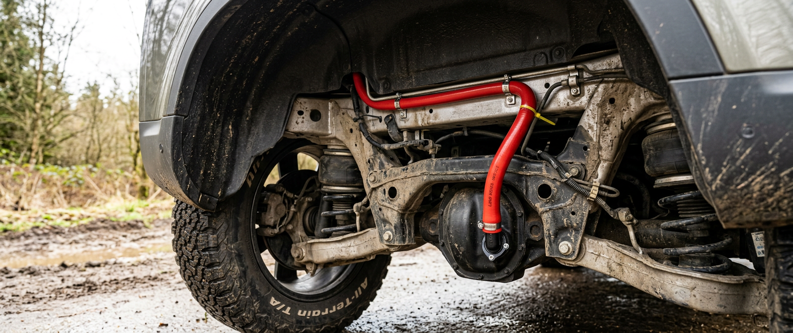
The L663's front differential breather is a semi-rigid nylon line that routes upwards from the differential housing, terminating high in the engine bay along the left-hand side of the engine bulkhead near the brake booster. While relatively safe, it can be compromised in deep water if a wave flows over the hood. The rear differential breather is more vulnerable; it routes from the top of the rear differential housing and clips into the rear subframe structure, terminating at a height of approximately 750mm. This is well below the maximum 900mm wading depth, relying on a small, spring-loaded one-way cap to keep water out under static pressure.
The ZF 8HP transmission and the transfer case use separate breather lines that terminate in a shared bracket situated on the rear upper face of the engine cylinder block, close to the bellhousing split line. Accessing these points is incredibly challenging due to the tightly packed engine bay of the L663, particularly on inline-six mild-hybrid (MHEV) models like the D250, D300, and P400. To systematically extend these lines, you must trace each line back to its source, remove the factory check-valves, and integrate them into a centralized, elevated manifold system.
Splicing and Extending Breather Lines: Step-by-Step Integration
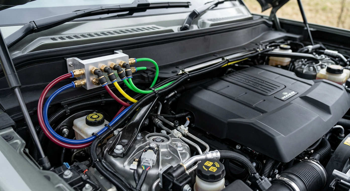
The most robust method for extending the L663 breathers is to replace the factory push-on caps with a centralized, multi-port pneumatic manifold routed to the highest point possible, such as the upper engine bay firewall or inside a sealed snorkel assembly. For this modification, use high-quality, flame-retardant Polyamide (PA12) or polyurethane (PU) pneumatic tubing with an outer diameter (OD) of 6mm or 8mm, alongside high-spec push-to-connect brass fittings. Do not use cheap vinyl tubing, which softens and kinks under engine bay heat, potentially sealing off a breather line and blowing out differential seals due to pressure buildup.
To extend the rear differential breather, safely raise the rear of the vehicle, support it on jack stands, and remove the rear left-hand inner wheel arch liner. Locate the breather tube where it clips to the subframe. Carefully cut off the factory plastic vent cap, retaining as much of the original hard plastic line as possible. Install a straight push-to-connect union or a high-temp silicone transition joiner secured with marine-grade 316 stainless steel worm-drive clips. Route the new extended line forward along the main chassis harness channel, securing it with heavy-duty UV-stabilized cable ties every 200mm, ensuring it is kept clear of moving suspension arms and the hot exhaust system.
Run this new rear line forward into the engine bay, routing it up the firewall. Next, access the front differential and transmission breathers from the engine bay. Cut off the factory termination caps, slide on push-to-connect reducers, and run these lines to a central anodized aluminum manifold block mounted high on the firewall. The manifold block should be fitted with a single, high-quality, splash-proof sintered bronze vent filter or routed via a single master line directly into the highest internal point of an aftermarket fully-sealed snorkel system. This layout guarantees that all drivetrain components breathe clean, dry air even if the engine bay is temporarily submerged.
Safeguarding the Electronic Air Suspension (EAS) Venting Path
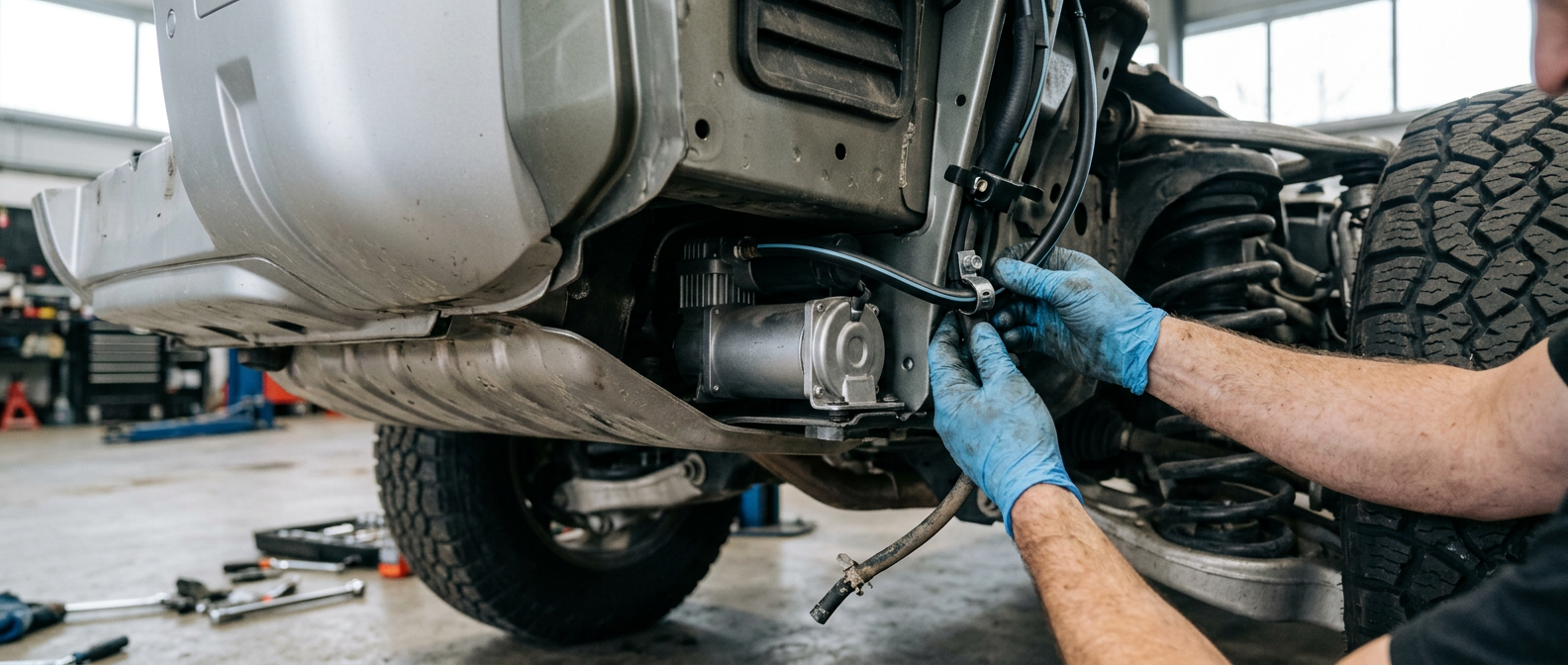
The electronic air suspension (EAS) system on the L663 is a highly sophisticated, closed-loop setup, but it is not entirely isolated from the atmosphere. The system utilizes an air compressor (manufactured by AMK or Dunlop depending on model year) located behind the rear left-hand bumper trim panel. This compressor draws intake air through a dedicated line that routes into the dry interior cabin space behind the C/D-pillar interior trim. This intake path is highly protected and rarely presents water ingress issues.
However, the compressor exhaust valve is a critical vulnerability. When the vehicle lowers or adjusts its ride height down, the system must exhaust pressurized air. The exhaust air travels out through an exhaust muffler/silencer assembly located within the rear bumper cavity. If the vehicle is submerged while the EAS system actively lowers or adjusts its trim (which it does automatically to maintain level), the compressor exhaust valve opens. If this occurs underwater, the sudden pressure drop can draw dirty water directly back into the compressor's drying canister and solenoid block, leading to internal corrosion, valve sticking, and ultimate system failure.
To mitigate this risk, you must relocate the compressor exhaust vent. Locate the exhaust silencer assembly behind the rear left-hand wheel arch. Disconnect the factory nylon exhaust tube from the silencer, and install an extension line using 6mm PU tubing. Route this line upward behind the rear light cluster assembly, terminating it high inside the upper rear quarter panel space or running it up to the roof line alongside the tailgate sealing channel. Fit the factory silencer/muffler to the end of this extended line to maintain quiet operation while isolating the exhaust path from deep water.
Waterproofing Low-Slung Electrical Connectors and Actuators
While Land Rover employs high-quality, sealed automotive electrical connectors (such as TE Connectivity and Delphi waterproof series) across the L663's EVA 2.0 electrical architecture, real-world off-road exposure can degrade these seals. Repeated heat cycling causes plastic connector housings to expand and contract, which can draw in micro-droplets of water over time. Low-slung systems are particularly vulnerable, including the electric power steering (EPS) rack, the ride height sensors at each wheel arch, and the active rear locking differential actuator.
Begin by disconnecting the harness connectors on the ride height sensors. These sensors are Hall-effect units that operate on a delicate 5V reference circuit from the chassis control module; even slight water ingress will cause resistance fluctuations, throwing immediate suspension fault codes. Clean the connector pins with contact cleaner, allow them to dry, and apply a small amount of non-conductive, high-viscosity dielectric grease (such as Dow Corning Molykote 111) to the rubber seal faces. This grease acts as a hydrophobic barrier, preventing capillary action from drawing moisture past the silicone seals under hydrostatic head pressure.
The front electric power steering (EPS) motor and rack assembly is mounted low on the subframe. While the main housing is sealed, the rubber boots protecting the steering rack shafts must be inspected for tears or loose securing clamps. If water enters these boots, it will corrode the internal rack teeth and destroy the EPS motor's internal encoder. Ensure the factory spring clamps are tight, or upgrade them to high-tension stainless steel Oetiker ear clamps to guarantee a completely watertight seal under high-pressure water blasting or deep wading.
Post-Wading Maintenance Protocols and Fluid Audits
No matter how thoroughly you prepare your L663 Defender for deep wading, water can still find its way past seals if the vehicle is submerged for extended periods. A rigorous post-wading inspection routine is essential to prevent long-term drivetrain damage. Within 48 hours of completing deep or prolonged crossings, perform a comprehensive visual audit of the vehicle's underside, checking for signs of water ingress, mud packing around heat shields, and debris caught in the brake assemblies.
The most critical check is the condition of the differential oil. Because the L663 differentials do not have traditional dipsticks, you must check the oil via the fill plugs. Carefully clean the area around the rear differential fill plug to prevent dirt from entering, then remove the plug. Use a clean plastic syringe or zip-tie to draw a small sample of the lubricant. If the oil appears milky, cloudy, or has a yellowish-brown emulsion layer, water has bypassed the seals or the breather system. The differential must be drained and flushed immediately with the correct specification lubricant (such as Castrol BOT 720 for locking diffs or SAF-Carbon Mod for open variants) to prevent accelerated gear and bearing wear.
Finally, thoroughly wash down the radiator, intercooler, and auxiliary cooling stacks located behind the front bumper. Silt and mud deposited during wading will dry and bake into the aluminum cooling fins, drastically reducing heat transfer efficiency and leading to engine overheating under load. Use a low-pressure garden hose directed from the engine bay outward to flush out debris; do not use a high-pressure washer close to the cooling fins, as this will bend the delicate aluminum fins and permanently restrict airflow.