L663 Coil Suspension Upgrades: Spring Rates, Geometry, and Installation
A technical guide for DIY mechanics looking to upgrade the coil-sprung L663 Defender. Learn how to calculate spring rates for constant loads, select high-performance dampers, and correct geometry to maintain factory wheel alignment.
The L663 Coil-Spring Architecture: Limits of the Factory Setup
While air-sprung variants dominate the L663 Defender lineup, the coil-sprung models—predominantly found on base-spec 90s, 110s, and commercial Hard Top variants—offer a robust, mechanically simplified platform. Factory coil setups utilize a double-wishbone front suspension and an integral-link independent rear suspension. Although highly capable out of the box, the OEM suspension is tuned primarily for unladen passenger comfort, featuring linear-rate front coils and mildly progressive rear coils designed to keep the vehicle level under nominal loads.
The limitation of this factory setup becomes apparent when owners begin outfitting their vehicles for self-sufficient travel. Adding steel front bumpers, recovery winches, drawer systems, and portable refrigerators introduces a constant, static payload. Under this continuous weight, the factory springs sag, drastically reducing positive suspension travel (compression or bump travel). As the ride height drops, the vehicle relies heavily on its microcellular polyurethane bump stops, leading to a harsh, jarring ride over minor road imperfections and significantly degraded off-road articulation.
Upgrading the coil suspension is not merely about gaining ground clearance; it is about restoring the vehicle's dynamic load capacity and maintaining the balance between compression and rebound travel. When choosing aftermarket springs, owners must distinguish between linear and progressive-rate coils. Linear coils maintain a constant spring rate throughout their compression stroke, which is ideal for predictable handling under a fixed, unchanging load. Progressive coils feature variable pitch winding, starting soft to absorb minor road chatter and stiffening dynamically as the suspension compresses under heavy payloads.
Spring Rate Dynamics: Calculating Your Constant Load Requirements
Selecting the correct spring rate requires an accurate assessment of your vehicle’s constant load. Estimating load incorrectly leads to two common failure modes: an excessively stiff suspension that limits articulation and ruins ride quality, or an under-sprung suspension that sags and quickly wears out the dampers. To determine your requirements, you must calculate the distribution of your accessories relative to the front and rear axles. A winch and steel bumper sit far forward of the front axle centerline, creating a leverage effect that increases the effective front wheel rate.
Factory L663 front coil springs typically feature a rate of approximately 500 lbs/in (87.5 N/mm). If you install a winch bumper and steel underbody protection, you add a constant 60 to 80 kilograms of dead weight directly over the nose. To offset this without altering the original ride height, an upgrade to a spring rate of 550 to 600 lbs/in (96 to 105 N/mm) is required. Aftermarket manufacturers like Eibach and Old Man Emu design heavy-duty front coils specifically for this purpose, preserving suspension travel and preventing nose-dive under hard braking.
At the rear, the calculation is more complex due to the varying payloads carried by touring setups. The standard rear coil rate starts at a soft progressive wind of around 450 lbs/in (78.8 N/mm) and climbs to 600 lbs/in (105 N/mm) under deep compression. For a permanent drawers-and-fridge setup, or a constant payload exceeding 250 kilograms, heavy-duty rear springs with a continuous progressive rating of 600 to 750 lbs/in (105 to 131 N/mm) are recommended. These higher rates maintain the standard unladen ride height under load, ensuring that your headlamps remain correctly aligned and your steering geometry is not compromised by a tail-heavy bias.
Damper Selection: Controlling High Unsprung Mass
The L663 Defender features massive cast-aluminum suspension knuckles, heavy multi-link control arms, and large-diameter wheel and tyre combinations. This creates a high unsprung mass, which requires exceptional damping control to manage. When you fit stiffer aftermarket coils, the spring's potential energy increases. The damper (shock absorber) must have sufficient rebound valving to control this energy and prevent the vehicle from bouncing repeatedly after hitting a bump. Standard twin-tube dampers are prone to oil foaming (aeration) and subsequent fade under high-frequency cycling, such as corrugated dirt roads.
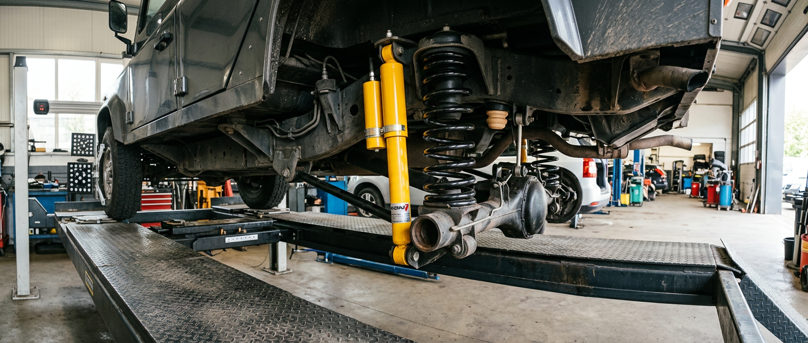
For owners looking to upgrade, monotube gas-pressurized dampers, such as the Bilstein B6 Offroad series, are a highly effective option. Monotube dampers house the working oil and high-pressure nitrogen gas in a single cylinder, separated by a floating piston. This design provides superior heat dissipation because the oil is in direct contact with the outer steel body, virtually eliminating shock fade. Furthermore, the larger piston diameter in a monotube shock allows for more precise valving adjustments, offering firmer control over low-speed body roll without introducing high-speed harshness over sharp rocks.
Alternatively, heavy-duty twin-tube dampers with large fluid capacities, such as the Koni Heavy Track Raid series, are favored by long-distance tourers. These dampers feature an outer reservoir tube that protects the inner working cylinder from rock strikes and mechanical damage. They prioritize oil volume over absolute cooling speed, providing a reliable, long-travel damping solution that is less susceptible to internal pressure spikes. Whichever design you choose, the damper must be matched to the spring rate; running heavy-duty springs on worn or factory-valved dampers will quickly overheat and destroy the shocks' internal seals.
Suspension Geometry: Correcting Camber, Castor, and Roll Centers
Modifying the ride height of an independent front and rear suspension (IFS/IRS) vehicle like the L663 inevitably alters its suspension kinematics. When you lift a coil-sprung Defender by 30mm to 50mm using taller springs, the control arms swing downward and inward. This movement pulls the top of the wheel knuckles outward, introducing positive camber and reducing the negative camber required for stable cornering. It also decreases front caster, which can make the steering feel light, twitchy, and prone to tramlining on the highway.
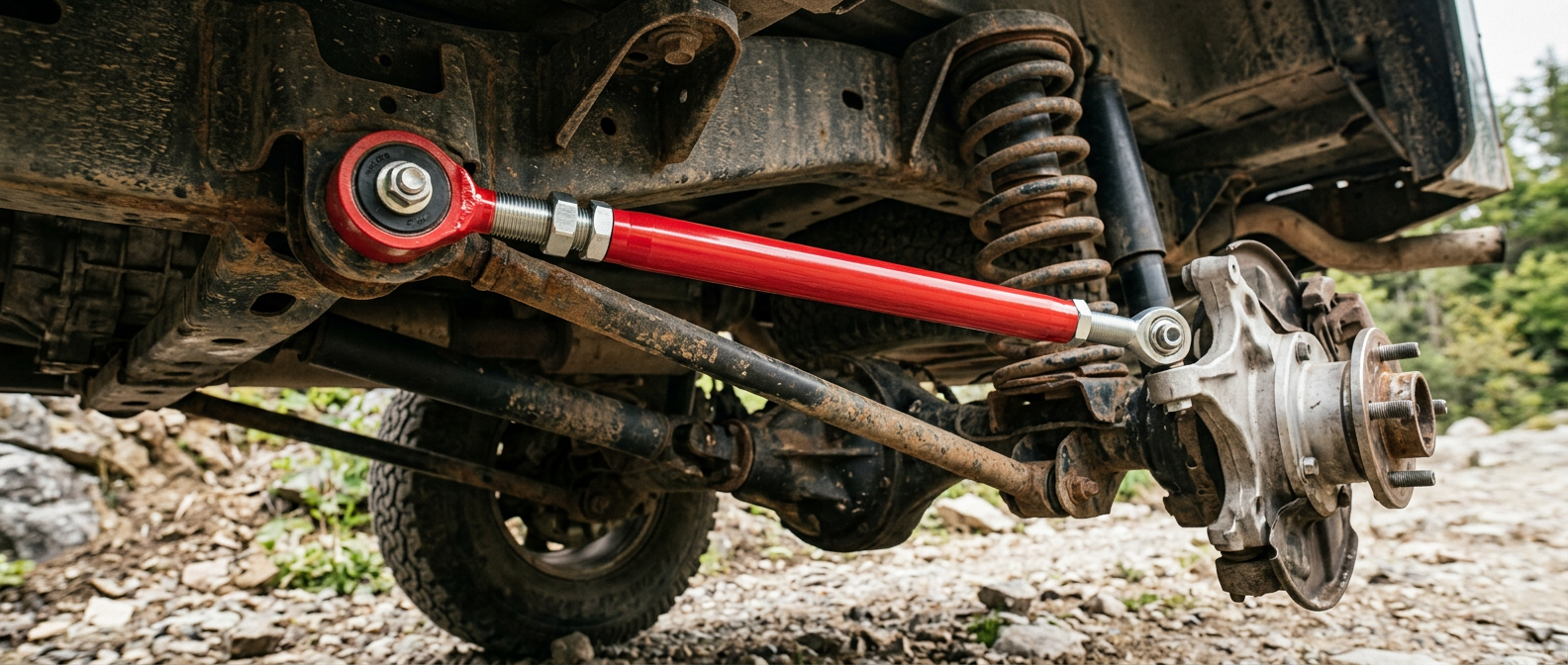
To correct these alignment issues, any lift exceeding 35mm requires specialized geometry correction components. At the front, adjustable upper control arms (UCAs) are essential. Aftermarket UCAs are designed with corrected ball joint angles to prevent binding at full suspension droop and feature offset geometry to restore factory caster angles. This ensures that the tyre tread maintains flat contact with the road surface during cornering, preventing accelerated outer-shoulder wear and preserving the vehicle's natural self-centering steering feel.
At the rear, the L663's integral-link setup is highly sensitive to height changes. Raising the rear suspension increases toe-in and introduces positive camber. The factory eccentric adjustment bolts do not offer enough range to correct this deviation on lifts over 40mm. Installing adjustable rear upper control arms (often referred to as camber arms) is the only reliable way to pull the top of the rear knuckle back into specification (aiming for -0.5° to -1.0° of camber). Proper alignment ensures the rear tyre contact patch is maximized, which is critical for traction when climbing loose, off-road terrain.
Step-by-Step Installation: Tooling, Safety, and Common Pitfalls
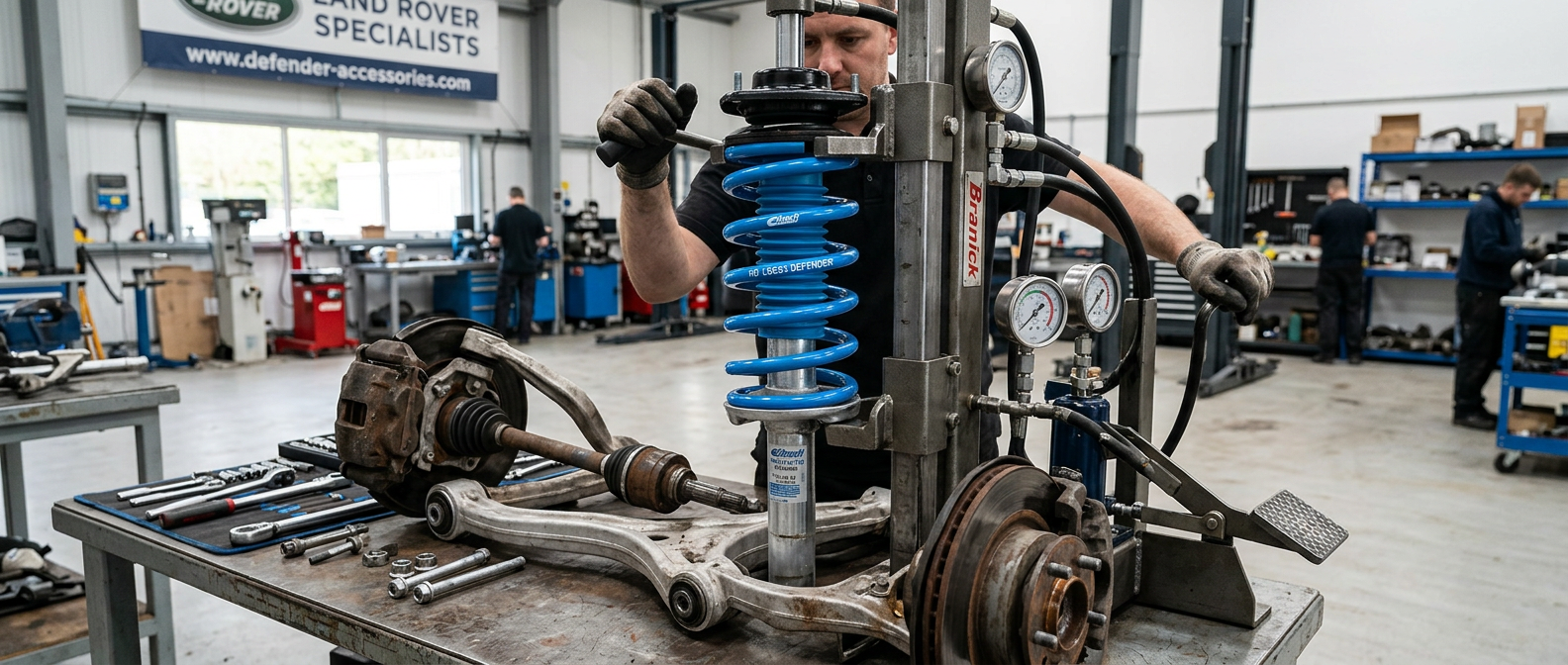
Upgrading the suspension on an L663 is a physically demanding task that requires specialized tools. First and foremost, you must use a high-quality, heavy-duty hydraulic or mechanical strut compressor. The front struts on the L663 carry an immense amount of pre-load; using cheap, universal hook-style spring compressors is highly dangerous and can result in catastrophic tool failure. Additionally, ensure you have a complete metric socket set (including 18mm, 21mm, and 24mm sizes), a torque wrench capable of reaching 300 Nm, and a ball joint separator tool.
To remove the front strut assembly, support the vehicle securely on chassis stands. Remove the wheel, disconnect the sway bar end link, and unbolt the outer tie rod end. Loosen and remove the upper control arm ball joint nut from the knuckle. Support the lower control arm with a hydraulic jack to prevent it from dropping suddenly, then remove the lower strut clevis bolt. When lowering the assembly, be extremely careful not to over-extend the inner constant velocity (CV) joints; if the inner triple-roller bearing pops out of its cup, it will require a full axle teardown to repair.
The rear strut removal presents a different challenge: interior trim removal. Unlike traditional 4x4s where the shock mounts are externally accessible, the L663's rear strut top mounts are located inside the cabin, behind the rear wheel arch trim panels. On 110 models, you must carefully remove the rear cargo floor, the D-pillar trim, and peel back the carpeted side panels to access the three 15mm upper mounting nuts. Take your time with the plastic trim clips to avoid snapping them, and always use plastic trim removal tools to prevent scratching the interior panels.
Torquing at Ride Height and Post-Installation Calibration
The single most common mistake made during suspension installation is torquing the suspension bolts while the vehicle is suspended on a two-post hoist. The L663 uses bonded rubber-to-metal silentbloc bushings in almost all of its suspension pivot points. If you tighten the pivot bolts while the suspension is fully extended (in a drooped state), the rubber bushings will lock in that position. When the vehicle is lowered back onto its wheels, the bushings are forced to twist excessively just to reach normal ride height, leading to rapid tearing, squeaking, and premature bushing failure within a few thousand miles.
To prevent this, leave all control arm, strut lower mount, and sway bar link bolts finger-tight during assembly. Once the vehicle is fully assembled, lower it onto its wheels on a level surface. Jounce the front and rear bumpers several times to settle the suspension to its natural ride height. Only then should you slide under the vehicle with a torque wrench and tighten all fasteners to their factory-specified torque values (for example, the front lower strut-to-arm bolt requires 175 Nm + 90 degrees). If access is tight, drive the vehicle onto drive-on ramps to gain workspace while maintaining the suspension under load.
Following the installation of new coils and dampers, the steering angle sensor (SAS) must be recalibrated. Because the physical steering wheel position relative to the road wheels will change slightly due to the lift, the vehicle's dynamic stability control (DSC) system may interpret this as an uncontrolled slide and intervene unexpectedly. Drive the vehicle directly to a professional alignment shop equipped with a modern 3D wheel alignment system. Once the physical alignment is locked in, use a compatible OBD-II diagnostic tool to reset the SAS and clear any temporary chassis fault codes.