Safely Tapping the L663 Defender Electrical System: CAN-Bus, LIN-Bus, and EVA 2.0 Integration
Integrating aftermarket accessories into the L663 Defender requires a deep understanding of Land Rover's sensitive EVA 2.0 electrical architecture. Avoid costly DTCs, limp mode, and parasitic battery drain by learning how to safely extract signals, utilize contactless CAN-bus readers, tap clean ignition triggers, and respect the vehicle's complex power-down cycle.
Understanding the EVA 2.0 Architecture and the Risk of Traditional Tapping
The L663 Land Rover Defender represents a monumental leap forward in vehicle networking, departing completely from the relatively simple electrical layouts of legacy utility vehicles. It is built upon Land Rover’s Electronic Vehicle Architecture 2.0 (EVA 2.0), a highly complex system consisting of up to 85 separate Electronic Control Units (ECUs) communicating via high-speed CAN-FD (Flexible Data-rate), LIN (Local Interconnect Network), FlexRay, and automotive Ethernet. In this ecosystem, every circuit is actively monitored by the Body Control Module (BCM) and Gateway Module (GWM) for voltage drop, current draw, and resistance profile.
Attempting to wire auxiliary equipment—such as driving lights, UHF radios, air compressors, or travel fridges—using traditional off-grid methods is a recipe for system-wide failure. Splicing into a factory tail-light wire for a reverse signal or piercing a headlight high-beam feed to trigger a relay changes the resistance of that circuit. The BCM immediately flags this as a short-circuit or unexpected current draw, shutting down power to the circuit to protect the hardware and logging a diagnostic trouble code (DTC). In severe cases, tapping the wrong data-carrying wire can corrupt the CAN-bus signal packets, causing intermittent communication dropouts, dashboard warning lights, or forcing the vehicle into limp-home mode.
Contactless CAN-Bus Readers: Extracting Signals Safely
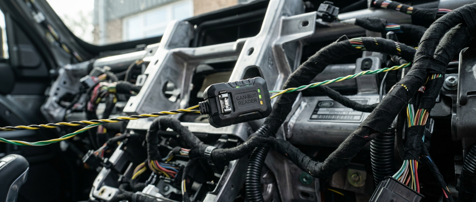
To safely trigger accessories like high-output driving lights or winches that must function in sync with factory controls (such as the high-beam stalk or reverse gear), you must read the digital command sent across the vehicle's network rather than looking for a physical 12V output. The safest way to achieve this on the L663 is with an inductive, contactless CAN-bus reader. These devices clamp around the factory twisted-pair CAN wires and read the data packets electromagnetically through the wire's insulation, requiring no copper-to-copper splicing, soldering, or physical modification to the factory harness.
To install a contactless CAN reader, you must locate the correct network wires. In the L663, the chassis or body CAN-bus wires are typically accessed behind the glovebox assembly or behind the passenger-side lower kick panel. Look for a tightly twisted pair of wires; the high-speed CAN-bus pairs have a precise twist-rate of approximately 33 twists per meter to mitigate electromagnetic interference. Once identified and verified with an oscilloscope or high-impedance digital multimeter, the contactless reader is clamped over the wires. It decodes the network traffic and translates the digital high-beam or reverse command into a clean, low-current 12V output that can safely switch an aftermarket relay.
Locating and Utilizing Safe 12V Ignition Triggers
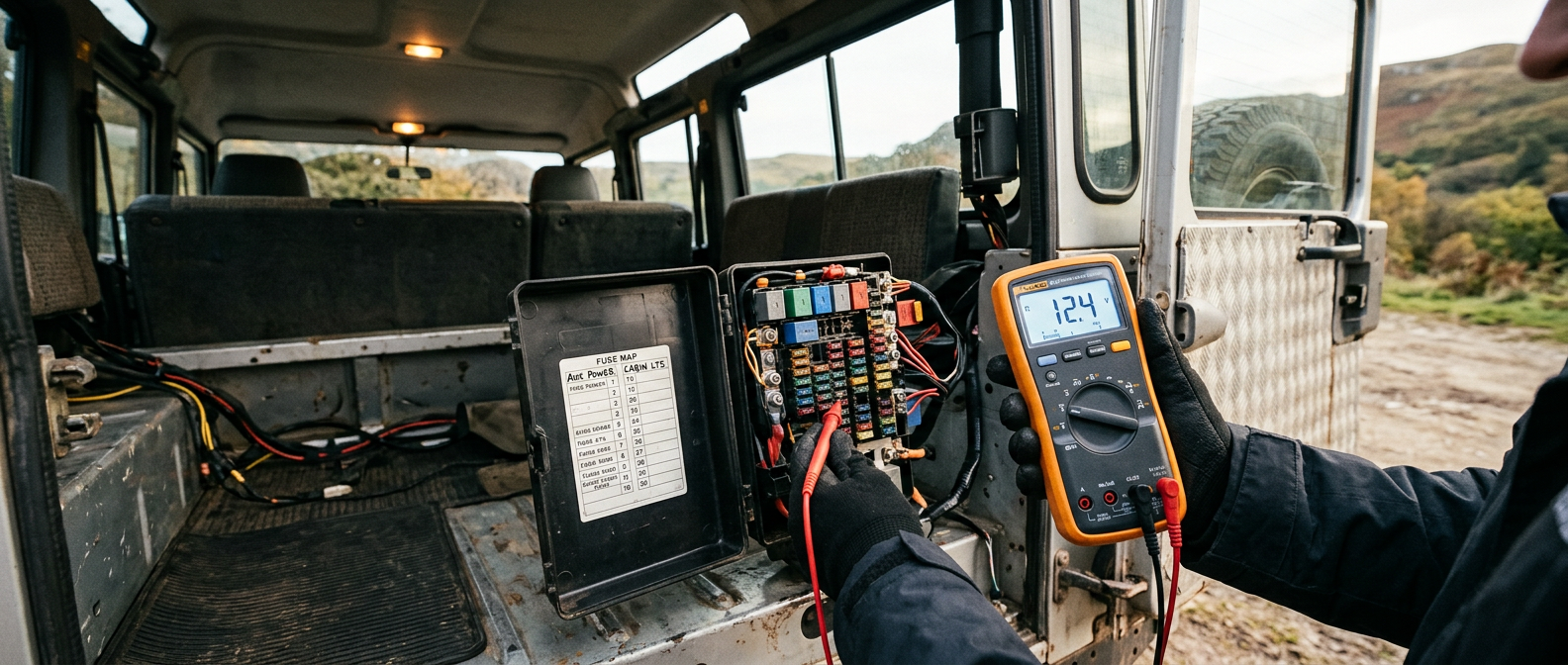
Many accessories require a switched ignition trigger (often referred to as a KL15 run/start signal) to ensure they only operate when the engine is running or when the vehicle is fully awake. Tapping the wrong fuse or wire can prevent the vehicle's ECUs from entering their designated sleep states, leading to rapid battery depletion. The primary power distribution centers in the L663 are the Engine Compartment Fuse Box, the Passenger Footwell Fuse Box (FJB), and the Rear Junction Box (RJB) located in the loadspace.
For inside-the-cabin accessories, the safest physical ignition tap point is the circuit designated for the 12V auxiliary power outlets (the cigarette lighter sockets), typically located in the RJB or FJB. These circuits are designed with built-in time delays managed by the GWM, turning off power exactly 10 to 15 minutes after the ignition is switched off and the vehicle is locked. When using a fuse tap (or 'add-a-circuit') in these blocks, always ensure the tap is inserted in the correct orientation so the accessory draw runs through its own dedicated fuse and does not bypass the factory circuit protection.
Managing Shutdown Cycles and Parasitic Battery Draw
A common issue L663 owners face after installing aftermarket electronics is a 'Battery 2 Low' warning on the instrument cluster. The EVA 2.0 system monitors state-of-charge via a Battery Monitoring System (BMS) sensor on the negative battery terminal. When you park and lock the vehicle, it does not shut down instantly. Instead, it enters a multi-stage shutdown cycle. During the first 10 to 20 minutes, the network modules communicate and run self-diagnostic checks, drawing up to 5 to 10 amps. Gradually, the modules are instructed to enter a 'deep sleep' mode, dropping the total parasitic draw of the vehicle down to a minuscule 10 to 30 milliamps.
If an aftermarket accessory is wired in a way that leaks voltage back into a monitoring circuit, or if it draws its power directly from a permanent 12V source (KL30) while grounding to a chassis point that bypasses the BMS sensor, the vehicle's modules will detect this anomalous current loop. Consequently, the GWM will refuse to let the ECUs sleep, keeping the high-speed networks active indefinitely. This results in a continuous parasitic drain of several amps, flattening the main starter AGM battery within 24 to 48 hours. Always run accessory ground wires back to the designated factory chassis ground points located upstream of the BMS sensor, never directly to the battery's physical negative post.
Wiring Auxiliary Switch Panels Independently
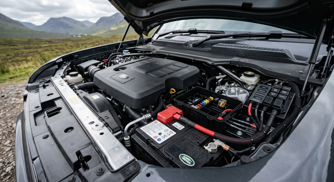
To avoid interfering with the EVA 2.0 network altogether, the most robust solution for managing multiple heavy-draw accessories is to install an independent, solid-state auxiliary switch system (such as a Garmin PowerSwitch or an Auxbeam controller). These systems consolidate all accessory switching outside the factory network, requiring only a single heavy-gauge power connection to the battery, a solid chassis ground, and a single low-current ignition trigger.
The primary battery on the L663 is housed beneath the front right seat (or front passenger seat depending on market and drive-hand configuration). Rather than attempting to run multiple heavy wires directly through the tight seat-base seal, installers should utilize the high-current distribution studs located in the engine bay under the plastic engine cover, or the dedicated auxiliary power terminals provided in the rear quarter panels of utility-spec models. The auxiliary switch control module can be mounted securely in the engine bay or loadspace, with wireless or low-voltage control lines routed to the driver's compartment, completely isolating your off-road accessories from the delicate digital nervous system of the vehicle.